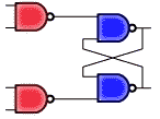
 The logic circuit shown represents most closely the architecture of a
2 is CORRECT. This circuit is the SR latch with enable. The left-most gates would have inputs S and E for the top gate and E and R for the bottom gate. The rightmost cross coupled gates form a latch circuit and would have outputs Q and Q.