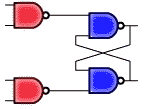
 The logic circuit shown represents most closely the architecture of a
3 is WRONG. The D latch with enable is similar to this circuit, having the same four NAND gates, but uses an additional inverter to complement the input. In this case the inputs to the top NAND leftmost gate would be D and E, while the inputs to the bottom leftmost NAND gate would be E and D.